Zaph|Audio - ZA5 Speaker Designs with ZA14W08 woofer and Vifa DQ25SC16-04 tweeter
Zaph|Audio ZA5 Family
INTRODUCTION
Welcome to the Zaph Audio ZA5 project page. The ZA5 family is a group of related designs based on the Zaph Audio ZA14W08 woofer and the Vifa DQ25SC16-04 tweeter. These are high performance and low cost drivers. Both drivers are available at Madisound, along with these designs sold as kits.
The designs range from a tiny sealed 2-way to a tall multi-driver vertical array. While each design serves a slightly different purpose that will be discussed individually below, there are some commonalities between them which we will go over in this preface.
All of these designs will work well run full range at low to medium levels. By design however, the woofers are not bass monsters because tradeoffs have been made in favor of midrange and midbass smoothness and clarity. Those who require higher levels or home theater usage will generally need a subwoofer. Consider a pair of the new Seas L26ROY if you have the money, or something from the Peerless SLS line if you need good value along with good performance.
The crossovers for these designs are different, but share some similarities. All are mildly asymmetric LR4. In general, the more midwoofers in the design, the higher I cross over to the tweeter as a trade off between optimal woofer bandwidth and tweeter power handling. All of the crossovers use a tiny cap across the first woofer inductor as a trap circuit to kill the breakup a bit more. And finally, all have some tweeter adjustability to account for batch to batch level variation along with personal preference. I specify all Caps as Bennic poly, all larger series inductors as Sledgehammer Steel Laminate, and all other inductors as basic cheap air cores. I don't care what resistors you use, as long as they are 10 watt rated or higher. Madisound may offer upgrades for those who believe that costlier crossover components make an audible difference.
The kits sold at Madisound will come with assembled crossovers. Note that the resistors may vary in brand and be close values or paralleled to reach a value. Aside from that, my own preference of brands will be used. Madisound kits have a vented options package that will provide foam damping material to install on 5 internal sides. Double up on the top, back and bottom. The sealed ZA5.2s offers enough Acousti-stuf to do the job, while the vented ZA5.5tt will also include some Acousti-stuf to be placed on the bottom. Ports in these kits will come the right size and not need to be cut.
ENCLOSURE STANDARDS & TUNING OPTIONS
All designs use an 8" wide enclosure and all have the tweeter centerline 2.63" from the closest cabinet edge. This means there will be similar driver response curves for all systems with the primary difference being the usual cavity effect on the tweeters mounted between woofers in the MTM style arrangements. Hole size and countersink information is available below. These dimensions are accurate enough that you don't have to have the drivers in hand to build your enclosures.
All enclosures shown in the designs use the same volume and tuning per woofer - 10 liters (or approximately .38 cu ft) and 52 hz tuning with various port configurations. It's about 9.3 liters after the volume of drivers, bracing and port are taken out. There are many tuning and enclosure volume options to consider however. First let's go over how I chose the default tuning and volume.
Choosing a tuning is a fine balance of power handling, extension and realistic in-room usage. Many people choose a tuning based on the lowest anechoic F3 possible, without considering the effects of the primary series inductance and the baffle step. This is shown as the basic uncompensated tuning above. You can model and design by an anechoic and unfiltered curve, but it's generally not realistic except for an infinite baffle installation with an active crossover. Considering where the average primary room node falls, I usually go for a gradual low end rolloff to help the in-room curve avoid boomy one-note bass. After the series inductance and baffle step is added to the model, I reach my goals. The full simulation above what I arrived at. The real measurements match pretty well.
There are other options, such as sealed in a 7 liter and vented in the same enclosure, or roughly about 6.5 liters after everything's in the box. These are shown above in a simulation including baffle step, diffraction and series inductance. Sealed rolls off pretty early and will not have satisfying extension without a subwoofer. Vented with a higher tuning of 65 Hz will give more output in the 80-120 range but have severe power handling issues as the woofer unloads whenever music with sub-60 Hz content comes along. And finally the lower tuning of 52 Hz in this enclosure doesn't quite result in the extension of the 10 liter enclosure, but it's close enough that you could build with the 7 liter if size is an issue. If you choose a smaller enclosure, be sure to keep the same baffle width and tweeter location relative to the woofer and nearest edge.
POWER HANDLING & SUBWOOFER CONFIGURATION
Power handling will always be very important in a system using only a 5 inch woofer and here is a look into various options. All plots above are a simulation including baffle step, diffraction and series inductance with power doubling starting at 1 watt up to 128 watts. Plots are for full range usage without a subwoofer crossover.
These are "full featured" power handling sims that include the speaker's modeled rolloff along with the active filter's rolloff. Plots are for 1 woofer only so multidriver systems affect the maximum output accordingly. When a subwoofer highpass filter is used, you'll notice that excursion limitations are roughly the same for both sealed and vented, and happen around 100 Hz for an 80 Hz highpass and about 120 Hz for a 100 Hz highpass. Generally, if you use a 100 Hz sub crossover, a single 5" will handle most of what an average 100 watt HT receive can give. If you are running the 10 liter 52 Hz vented system full range with no sub, above tuning you will reach excursion limits with about 20 watts at 70 Hz.
Something to keep in mind is that active subwoofer filters sum with the system's natural rolloff for somewhere between 4th and 6th order overall. Assuming your sub crossover can't do asymmetrical slopes (most are LR4 highpass and lowpass) be ready to play with both phase control and placement to get the best integration. Alternatively, you could enable the plate amp's internal filter. For example, a sealed satellite speaker with a natural 2nd order highpass at 100 Hz, used with a sub and amp with a 2nd order lowpass at 100 Hz, and additionally filtered with an HT receiver's LR4 highpass and lowpass will give you a symmetrical LR6. The unfiltered LFE input on a sub amp is not always the best option. There's even more to it than that - you may have to overlap or underlap your corner frequencies to compensate for room nodes. If you don't have measurement ability, be ready for a lot of experimentation.
If lower sub crossover points aren't giving you the power handling and output you need, and bigger mains are not an option, you'll have to cross higher. In those situations I always recommend 2 subs with one on each side to help mask the sub's location that is normally given away by tall order harmonic distortion. A single sub with a higher crossover point will almost always tilt the midbass tonal balance in it's direction unless you can manage to put it directly in between the satellites.
| ZA5.2 - TM vented 2-way | 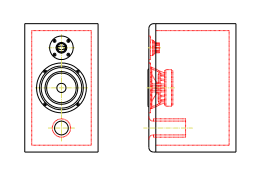 |
This design is very smooth, clean and versatile. The Vifa tweeter is crossed over relatively low, since the woofer will be the power handling limitation under common usage. Vertical polar response is tall enough that this system can be used on it's side for a center channel. Nobody wants an "upright" center channel, so horizontal usage was a requirement. A tall vertical window while upright is a good horizontal off axis response while on it's side. Dialog should be clear enough with a +/- 30 degree window. Most center channel applications will require the reduced baffle step option, as will those used close to boundaries. Up against a wall or on a shelving unit for example. Additionally, the reduced BSC option is your best bet if your HT layout requires placement right next to a TV screen. But if you can keep at least a foot between the TV and the speaker, and a couple feet from the rear wall to the front baffle, the standard design will work. |
|---|
| ZA5.2s - TM sealed 2-way | 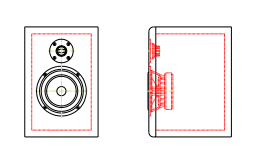 |
While the plots on this web site are all done with the 10 liter enclosure, 7 liters is an option also. Both sealed and vented will work in this enclosure. Choose your low end rolloff and take your pick. See the "enclosure standards & tuning options" section above. This is essentially the Madisound MD7.5B enclosure if you want a quick and easy option. All design data shown in the larger enclosure above is still applicable, including the reduced baffle step compensation option. |
|---|
| ZA5.3 - MTM | 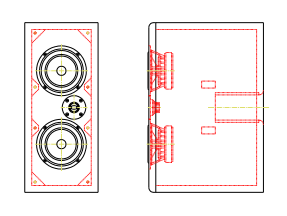 |
This MTM design is a solid 4 ohm system with the additional woofer increasing the maximum output level and lowering distortion. Impedance drops to 3.8 ohms in the midbass, which is high enough that most cheap receivers could handle it. The ZA14W08 is a relatively high impedance woofer with 7.1 ohms DCR. These days even the cheapest receivers have thermal protection, so if you do find the limits there is little chance of damage. The tweeter is offset for a couple of reasons - first, to allow closer placement of the woofers, and second to keep the center to edge distance the same as the TM designs. The vertical off axis does have the typical MTM null based on woofer center to center distance, but the small tweeter and close placement of the woofers minimizes that effect and makes the overall sound closer to a point source. This minimizes the power response issue that makes many people dislike the sound of an MTM. The crossover frequency is a tiny bit higher than the TM design. This is a power handling concession to the tweeter. Given the higher output that a system with two woofers is capable of, more is asked of the tweeter and a more conservative crossover is required. It is a tradeoff with the optimal operating range of the woofer. As we add more woofers to a design, overall distortion lowers and breakup related distortion becomes less of an issue, keeping the 3rd and 5th order harmonics below the audible radar. That is how these trade offs are balanced. The one negative of this design is some raggedness in the tweeter response as compared to the TM versions. This is caused by cavity effect of the two close mounted woofers and it is a typical symptom of the MTM layout. In this case, it causes a peak/dip combo between 3 and 4 kHz. The peak is addressed in the crossover and a small amount of the dip still shows up in the final system response 3 and 5 kHz. That dip on axis is hardly objectionable and for some, it's a preferable tonal balance. If you look at the horizontal off axis polar response, you'll see that it does not matter much if the tweeter goes to the inside or the outside. The droop due to woofer piston diameter is very mild, and identical on both sides. If I had to pick one arrangement, it would be tweeter to the inside. This MTM is what I would call a medium baffle step compensation design. If you need to place it close to boundaries or use it horizontally, please see the alternative design below. |
|---|
| ZA5.3c MTM Center channel |  |
This is a version of the MTM design done specifically for horizontal center channel usage. It is also workable as a near boundary or near TV design. You will hear many people say that a MTM is just not good for horizontal usage, and for the most part they are right. The problem is that upright center channels will not work with the average home theater layout, unless you are lucky enough to have a front projector with a sound transparent screen. But for most of the HT world, we've got to squeeze the center channel between the TV and the furniture it's mounted in/on. We can however optimize some of the typical MTM off axis response issues out of it, and give it a tonal balance that favors dialog. That is exactly what we've done here, and it's a completely different crossover rather than just an option based on the standard MTM. The crossover point has been dropped down a bit, though still not as low as the TM. There is very little baffle step compensation in this design, and the overall tonal balance favors a broad smooth rise through the upper midrange. The result of that can be seen in comparing the vertical polar responses between this and the standard MTM version. We've widened the listening window when this system is laid horizontal, and even when the response starts to droop due woofer center to center distance, a mild increase in the upper midrange minimizes the effect. The result is a horizontal MTM with a forward listening window of about 50 degrees from side to side. This is much more usable than the typical commercial center channel, which usually has serious lobing issues even 5 degrees off the horizontal axis. An MTM will never be as suitable as a W-T/M-W 3-way center, but here we've done our best with the format. Complaints of dialog audibility should be minimal. For those who must use the left and right MTM systems right up against the TV, this design is suitable for that also. With that standard MTM design I said it didn't matter much if the tweeter goes to the inside or outside, but for this system it does. The tweeter needs to mount away from nearby obstructions to avoid issues with reflections in it's operating bandwidth. If placed against the side of a TV, the tweeters should go to the outside. If used as a center placed on a shelf below the TV, in most cases tweeter up will be the best. The idea is to keep the tweeter side as clear as possible from nearby objects. For your left and right channels, If you have to place your enclosure right up against a wall, this is the design to use. Note that the ports face forward so they are not restricted by hi-fi furniture or the back wall. Most centers will need the ports on the front. But for the left and right, if the rears are at least 6" out from the wall, it's not going to matter either way. |
|---|
| ZA5.3t - TMM 2.5-way tower | 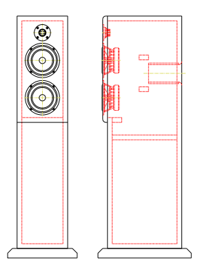 |
This TMM 2.5-way design is unique in this group and needs it's own crossover. It is essentially similar to the TM design, but with the full baffle step compensation inherent to a proper 2.5-way and all the typical benefits and handicaps of that arrangement. The only real handicap of a 2.5-way TMM is a non-symmetrical vertical listening window that has a bit of midrange droop above the normal listening axis. This is visible in the vertical polar plot. It is however fairly smooth and controlled off axis behavior and generally acceptable, even for those who want to hear a good tonal balance when they stand up. A side effect of this is a smoother transition into null below the listening axis at a shallower angle, with the direct benefit of less floor reflection through the midrange for better imaging. This system will still have most of the 300 Hz floor bounce dip, though it will be slightly less of an issue than a TM on a stand. This system will have the best tonal balance with some space around it, as used in medium to large rooms. In an HT system, keep it at least a foot away from the screen, the front of the baffle at least 2 feet out from the back wall, and at least 3-4 feet from the side walls. A front stage consisting of this TMM design on the left and right with a horizontal MTM (the ZA5.3c above) as the center is an acceptable combo, though you will have to lower the center level in the receiver controls a bit to match the left and right. Also note that while the drawing shows a floorstanding tower design, you don't have to build them that way. They can just as easily be stand mounts, and likewise, the other stand mounts on this page can easily be made into floor standers. |
|---|
| ZA5.5tt - MMTMM 2.5-way vertical array | 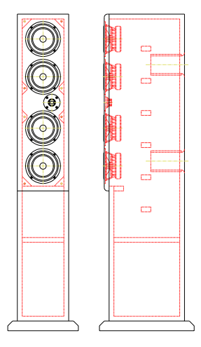 |
The ZA5.5tt is a 5 driver vertical array in a "tall tower" format. It is essentially an MTM modified into a 2.5-way system with the outer woofers rolled off early to do the baffle step compensation duty. This poses some unique control over power response that we will discuss below. Aside from that, distributing the output across 4 woofers in series parallel hookup gives us incredibly low distortion, high sensitivity and a relatively easy to drive impedance load. Unlike the other designs on this page, the design distance shown in the response plots is 2.5 meters. The system seems to work well down to 1.5 meters and of course the maximum distance is only limted by the output required to fill a large room. This system is 89 sensitive anechoic with 1 watt input and a solid 8 ohm nominal impedance, drooping to about 5 ohms for a small range between 2 and 3 kHz. There are no wild impedance swings and this system should be just fine for any amplifier, including tube amps. Thermal power handling is very high for this system, and provided the low end excursion is limited with a subwoofer crossover, this system should satisfy SPL requirements for almost anyone. The MMTMM 2.5-way format is all about controlled vertical directivity, and it's the reason I've been wanting to do one for a long time. Directivity is important overall, as is power response and other related issues. But different issues arise when considering vertical and horizontal directivity independently. Common CD (constant directivity) designs use a waveguide high frequency element and a traditional cone driven low frequency element. While the benefits higher in frequency are obvious, lower in frequency the system is just a point source. Good or bad, a point source is the type of sound radiation that is most affected by the room. Line arrays solve the vertical low frequency directivity issue through the brute force method. However, the cost and floor to ceiling design are obviously not for everyone. A MMTMM 2.5 way design can give you a lot of benefit without as much of the cost, while smoothing the transition to a point source tweeter in a way that a line array with a single dome tweeter can't. A MMTMM 2.5 way layout, unlike a MTM, does not have a fixed woofer center to center distance through the midrange to the low end. The effective woofer center to center distance gets wider as the frequency goes lower. This is caused by the outer woofer rolling in as needed to compensate for baffle step. As a result, provided the woofer spacing is thoughtfully laid out, vertical polar response is quite controlled between 300 and 1200 Hz, with a wider frequency spread of vertical lobing. A system like this would have far less floor and ceiling interaction in the lower midrange and midbass than an average 2-way or even a Waveguide CD design. Consider that the largest surfaces in any large room are going to be the floor and ceiling, and those surfaces are usually not an easy place to install surface treatments. The midbass and lower midrange is where the vertical directivity control is really needed. Higher frequencies are generally absorbed by the common carpet in a room. Room response curves are normally pretty rough for any system, sometimes +/- 10 db through the bass and lower midrange. This system by nature of it's vertical layout is quite a bit smoother in that range. There is not nearly as much of the typical floor bounce dip/peak combo at 300 and 500 Hz. Remember that room responses are different for everyone, but the floor bounce is generally similar. Also in these images, you can see why I generally prefer a rolled off low end - the primary lowest frequency room node is brought down in level to minimize a one-note low end. Note that this does not have to be built as a tower. It could be built without the bottom section and made a bit deeper to maintain volume. The obvious usage of that type of layout is for the person who has their TV (preferably a big flat screen) placed on a wide shelf or entertainment unit. Just be aware that this design is for larger rooms and needs a lot of room to operate. At least a foot or two away from the TV, a couple of feet out from the wall and the largest distance possible to the side walls. |
|---|
| ZA5.5t - MTMMM 2.5-way tower | 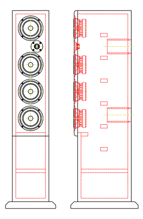 |
This design is essentially the same design as the MMTMM above, but made shorter by placing the top woofer on the bottom. Both .5-way woofers sit below a functional MTM. A 50" tall speaker is not for everyone, particularly those with pets or children and a fear of being crushed by a 120 pound speaker. The vertical polar response is all you really need to see to know what happens with the MTMMM configuration - much the same thing that happens with a more common TMM 2.5-way: a mildly drooping midrange above the listening axis. Creative builders could reduce this effect by building a sloped tower, putting the listening axis on or slightly below the 2nd woofer. Aside from that, the performance is very similar to the MMTMM version. |
|---|
| ZA5car - 2-way car system w/Seas 27TAFCG tweeter |  |
This infinite baffle design allows for use of the Seas 27TAFCG tweeter, which is a more appropriate choice for an automotive environment given it's small size and unique mounting. It is also a low distortion and high power handling tweeter that can cross very low. The crossover is about 1800 Hz, and lower allows for more placement flexibility in the car. These Seas small flange neo tweeters mount with a hole in the baffle then fasten from behind with an M4 bolt on the back of the magnet assembly. They are sold without any sort of cup, but it's relatively easy to use a piece of manually formed steel as a back clamp. The optimal tweeter and woofer arrangement for this design is with the tweeter being the same distance away from the listener as the woofer. The measuring distance to the woofer is the front plane of the cone and to the tweeter it is the mounting flange. There is about +/- 1" of distance placement flexibility in this design. However, in some instances, the tweeter may be hooked up in reverse phase and be placed 3-5" further away or 3-5" closer. The tweeter padding may need to be adjusted in these cases. A distance of 4" is equal to 180 degrees of phase at the crossover point, which is why you can make the system work with tweeter hooked up in reverse phase when the tweeter is in an appropriate location. The response is very smooth as shown, however these response plots are in a optimal infinite baffle configuration. The real world results may vary for every unique installation. At most however, a little tweaking of the tweeter padding resistor will be all that's needed. The crossover values on the tweeter look slightly odd with the larger values, however this topology works great for taming a tweeter with a peaking high Qts low end. The caps may be electrolytics if component size and cost as important. Electrolytics will not lower the sound quality, but they do have power handling limitations compared to poly caps. Looking at the transfer functions, you can see this design is close to 4th order. If you wish to do an active mid-tweeter crossover, set it to 4th order slopes with a center frequency around 1800 and tweak from there. No need to worry about the woofer breakup at this frequency, it will be sufficiently down in level enough to be off the audible radar. Having the woofer off axis to your ears certainly helps in this regard. Do not cross any higher than 2kHz actively unless your crossover has the ability to set up a sharp Q notch filter at 9 kHz. This system should not be considered a full range system, and will require an active crossover to a subwoofer. By design the woofer is closer to a midrange and in a automotive enviroment it does not have the excursion to cover the whole spectrum without the help of a subwoofer. A 4th order crossover between 80 and 120 Hz will do the job nicely and allow the ZA14W08 to reach very high output levels and operate without distortion. While the default power handling of the woofer is specified as 60 watts, that's merely a rough estimate in a typical vented home enclosure. With an active high pass subwoofer crossover filtering the lows, power handling will be substantially higher. For most people with an average SPL requirement, a 100 Hz sub crossover will do nicely. For those who favor very high levels, this driver will need to be crossed much higher, possibly as high as 150 Hz. That would be enough to satisfy almost any SPL requirement while operating with low distortion in the midbass and midrange.
|
|---|
| ZA5.2iw - 2-way in-wall system | 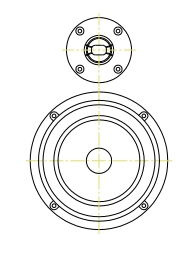 |
The ZA5.2iw TM and the ZA5.3iw MTM below are the in-wall versions of the primary designs shown above. They are based on the same design fundamentals however there is no box and they are mounted right in the wall. Be aware that this is the best solution if the listening room does not have room for a box design. This will have far better results than a "reduced baffle step" design in a rectangular enclosure placed up against the wall. The in-wall avoids the primary wall reflection that results from the depth of the enclosure, and will have a much smoother mid-bass response. A box mounted on a wall always has a large dip lower midrange and a peak in the upper midrange based on the distance of the baffle to the wall it's mounted on. There are however a different set of issues to be aware of with typical in-wall installations. For starters, drywall does not make a good baffle and wood is recommended. Enclosure rigidity is as important as it is in a box design, however in-wall it is magnitudes harder to have a rigid and non-resonant enclosure. For this reason, I would really only recommend the in-wall design in new buildings. That way the enclosure can be properly stiffened and damped as the wall is built. Most walls have 3.5" of depth and a chamber that goes from floor to ceiling. This is acceptable for the ZA5 in-wall design, however there needs to be a minimum of an inch of damping behind the driver, and lots of densly stuffed damping above and below all the way to the ceiling and floor. Without this, a lengthwise pressure node will develop and really screw up the bass response. This design, generally sealed in a large volume, will not have enough low end extension to operate without a subwoofer. A satisfying low end will require subwoofer implementation of your choice, be it infinite baffle or a more traditional box design near the wall. |
|---|
| ZA5.3iw - MTM in-wall left/center/right system | 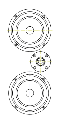 |
This design is similar to the 5.2 shown above but with the unique properties of an MTM - Higher sensitivity, higher power handling, higher output and lower distortion. Additionally, in the case of an in-wall with zero baffle step compensation required, this system is a solid 93 or 94 dB sensitive with a 4 ohm nomimal impedance. While users of this design will need an amp that is stable into 4 ohms, it certainly does not need to be a powerhouse. Please see the recommendations for wall damping, rigidity and system usage discussed in the ZA5.2 in-wall design above. |
|---|
ZA5 FAQ
(warning, some answers are long and technical)
Can the ZMV5 design be upgraded with the ZA14W08 woofer?
Yes, very easily. The woofer has the same frame, and the crossovers share similar parts. You will need to change out one resistor and add one small cap across the series inductor.
Can I use the MMTMM design horizontally as a center channel?
No, if you want people sitting off to the side to have clear dialog. The controlled vertical directivity of the MMTMM does not work well when laid on it's side. Additionally, all 2.5 way designs are inherently full baffle step compensation, and that will be too much midrange cut for a center channel typically mounted near a TV or in a cabinet. The MTM will work fine as a center channel with MMTMM's as the left and right mains. Power handling comparisons between the ZA5.3c and the ZA5.5 would be less of an issue than you might think, because the ZA5.3c does not have to reproduce as much in the bass range due to reduced baffle step compensation. Now, a WWMTMWW in a 3-way configuration using 6 ZA14W08's would work with the W's crossed very low to operate as a point source, but the crossover would have some huge values in it and overall it just seems a bit excessive.
What happens if the MMTMM woofer spacing is "thoughtlessly" chosen?
By that I meant that vertical directivity needs to be looked at as a design issue. This MMTMM format really works best with 5" or larger woofers because it results in a taller and wider enclosure and a more useful center to center spacing. When done with woofers smaller than that, some control over the low end vertical directivity is lost because the baffle step corner frequency is higher and the drivers are closer together making the system closer to a point source. You could of course build the baffle wider and taller while mounting small drivers in it, but most would see no point in that.
What's the difference between "controlled vertical directivity" and power response?
Vertical directivity is merely one component of power response. Power response is usually considered the whole package of off axis response combined into one average, though there are several definitions and standards. Breaking it down into vertical and horizontal elements can be useful however, because the speakers interact in the room differently in those directions. People have more control over boundaries on the horizontal plane but less control over floor and ceiling.
Floor and ceiling bounce issues are not discussed much. How important is this?
All early reflections should be avoided if possible. However, since everyone is forced to have a floor and a ceiling, the general consensus is that there is not much that can be done about it and therefore the issues are accepted as a necessary evil and are not a common topic of discussion.
What changes if I want to consider an open-back variant?
That would require a complete redesign. The ZA14W08 woofer could work well in a dipole or open back format, though you would have to pay very close attention to it's bandwidth and power handling. I'll leave a dipole design up to the DIY community, particularly since there are some folks out there that are much more experienced at that type of usage.
Why is sealed an option only for the TM and not the other variants?
Generally, a vented configuration is preferable for power handling reasons, even when using these with a sub. The smallest sealed enclosure option is only really recommended when enclosure size is an issue. Any of these designs would work in a sealed format, but without the extension and power handling gained around the tuning frequency.
Could you rank these as far as sound quality, in their various configs, compared to your previous kits?
Tough call, every design I do is different in some way. You can't just rank them, you have to consider your needs. "Sound quality" is too broad of a rating system. With an eye on value, all of the designs in the ZA5 series emphasize midrange clarity over all else. All will need a subwoofer to reach high output levels at lower bass depth. If you don't want a subwoofer, you might consider a design with a larger woofer and more full range output potential.
Why is the F3 on the MTM center channel 150hz?
That's the anechoic, freestanding F3, something you will never see in a real installation. The DIY community focus on the lowest possible anechoic F3 is largely misguided, mostly due to unrealistic use of simplistic box modeling programs. Room response and typical placement of a system always has to be considered. The MTM center channel response makes the bass droop look more substantial because a gradual rise is built into the midrange to bring out dialog and help compensate for horizontal off axis rolloff.
How come you didn't publish any 3-ways?
I wanted to limit my driver selection the ZA14W08 and DQ25 while leaving other options up to the DIY community. The ZA5 design family is really a showcase for these two high performance and low cost drivers. I do like the slim 8" wide enclosures, something generally not an option with large woofer 3-way systems.
Where should I mount the crossover?
With all of these designs, and most other designs, at the bottom of the enclosure works best.
Can you post a system harmonic distortion sweep for the systems you anticipate as most popular?
This has been done and will be posted shortly for the smallest system, the ZA5.2. It's more difficult to get useful harmonic distortion sweeps for larger speakers. As the design gets larger, the mic has to move back further to allow for proper summing. Further mic distances pollute the sweep with room artifacts. For example, a proper harmonic distortion sweep of the MMTMM system should probably be done at 2-2.5 meters in a full anechoic chamber to get a more meaningful comparison of the distortion improvement over the small 2-way.
Does the reduction in distortion through the use of multiple drivers occur linearly and proportionally to the number of drivers?
No. Non-linear distortion of a driver varies by output level, and does bear a relationship with level, at least through the midrange. But that relationship is not as predictable as one might guess. Doubling the number of drivers does not cut the non-linear distortion in half. Doubling (or quadrupling) the number of drivers does reduce the distortion, but it varies per driver and is mostly based on the motor. A theoretical perfect speaker will not have any reduction in distortion when used in multiples. But since even the best speakers are far from perfect, all have a reduction in distortion with multiple drivers. To be sure, cheap and simple motors will benefit more. This is good news for those who want to build line arrays with cheap drivers. As I mentioned in the answer to the previous question, it's a little difficult to do far field non-linear distortion testing for vertical arrays in a home environment, so to date I am still relying on my ears for that. I do indeed like what my ears are telling me about the ZA5.5tt system. Very clean and effortless.
The 5.2 enclosure drawing doesnt have any internal braces. Would it benefit from bracing?
A little but it's not required for a box that small. If you do want to add bracing to an enclosure that small, a simple 1" diameter hardwood dowel across the sides is all you need and anything else would be overkill.
Im sure the $13 tweeter sounds great, but compared to a $40 tweeter, how good?
Very good indeed. In fact, I chose this tweeter based almost completely on it's performance and it's small size. The fact that it only costs $13 is just a lucky bonus. To be clear though, value is important in all my designs. There are some other good small flange tweeters that perform a tiny bit better, but unfortunately they are very expensive.
The DQ25 has a rough top octave, should this concern me?
Not at all. People need to realize that a tweeter's performance is almost completely defined by it's low end. The range below 4kHz is where the ear is most sensitive to both linear and non-linear distortion. The human ear is unable to make out detail near the extremes of the audible range. This inability to hear details at the extremes of the audible spectrum allows us to accept the normally ragged in-room low end response of a woofer. (and we're talking +/- 5 or 10 dB here) In regards to frequency response aberration, the top octave is no different. There might be dips or peaks but you can't hear them. At most, you might only be able to tell if the top octave is there at all. Yes, I can tell if the response drops like a rock at 10kHz, but nobody, including younger folks with perfect hearing, will be able to tell if there's a 5 dB narrow band dip at 15kHz. But unlike woofers in the low bass range, where harmonics higher in fequency make subwoofers locatable, non-linear distortion becomes irrelevant higher in frequency because tall order harmonics are outside of the audible range. Given all this information, you can see that the DQ25 gives us great performance where it counts the most.
Can I use the MMTMM up against a wall? Can I use it in a wall?
No and No. The MMTMM is a 2.5 way design with full baffle step compensation. It needs lots of space around it to operate properly. Additionally, the crossover is specifically designed to work with the baffle. If you remove the baffle and place these in a wall, the response curve will get even further from optimal on top of the baffle step issue. Infinite baffle versions of the TM and MTM are available, but not
technically feasible for the MMTMM.
How would the ZA5.2 work as a nearfield monitor?
It would work great with a little tweaking. The better question might be "What are the specific requirements of a nearfield monitor?" There is a lot of noise about this question, and most of it wrong right down to definition of "monitor". Monitor = speaker, nothing more, nothing less. Everything else only amounts to environment differences. Nearfield is generally defined as 1 meter distance or less and may be as short as a half meter. The first issue is that the port needs to be front mounted. Placing a port on a rear effectively puts it too far away from the listener and lowers it's output relative to the front mounted drivers. Ports need to be tuned higher than normal. A gradual rolloff such as the one shown for the selected ZA5 tuning works great in-room with primary nodes that need to be tamed, but boundaries have much less of an effect in the near field so a flatter low end response is needed. Less baffle step compensation is needed to keep the system from sounding warm or muddy. This is not because of the nearby boundaries, but simply because the ratio of baffle width to the listening distance is a lot larger. And finally, nearby reflections should be avoided. For desk mounting, bring the tweeters up to ear level and provide some space between the monitor, side and back wall, even if it's just a few inches. The worst nearfield setup would be a desk in the corner with one speaker against the side wall - You're better off with headphones in that case. All of this in relation to the ZA5.2 would mean the following tweaks: using the reduced BSC crossover, using an enclosure of .25 cu ft, a front mounted port of higher tuning, maybe 55-65 Hz depending on taste.
Will the ZA5.3t - 2.5-way tower in an MTM configuration reduce the midrange droop above the listening axis on the polar response plots?
Yes, however the ZA5.3t is specifically designed to use a tweeter near the top edge of the cabinet. The tweeter response curve is different than when it is in a MTM cabinet. To be honest, when doing a 2.5-way design I preferred the tradeoffs of the TMM layout over the MTM layout. The primary benefit is a lower cabinet height and a tweeter response that does not suffer from MTM cavity effect. I think most will prefer that over the slightly improved midrange vertical polar response and that's why I didn't offer a MTM 2.5-way version.
I would like to be able to buy the ZA14W08 locally in [insert country]. Any plans to expand availability?
One of the reasons I chose Madisound as the distributor of the ZA14W08 woofer is that they have very good international shipping pricing. If you're in Europe, Asia or Australia and you've ever tried ordering from PE or MCM, you know what I'm talking about. I do not intend to ship directly to any other dealers besides Madisound. They are local to me and it helps for my post-manufacturing QC checks. Madisound does have a dealer program however, so if you would like your local dealer to carry the ZA14W08 woofer, have them call Madisound to discuss pricing and availability. Note that a bunch of guys on a forum wanting a group buy does not constitute a dealer. Also note that acceptance into Madisound's dealer program is subject to their approval, and larger quantity purchases are subject to availability.
For the ZA5.5tt, What is the location of the U13/14 and W15/16?
The W's are the .5 way speakers and should be on the outside of the MMTMM. The U's are are on the inside. In Soundeasy designing, the U's are for "upper midbass". I had to use that driver indentification and a particularly difficult (to figure out) node configuration to properly get the drivers to sum and give me accurate vertical lobing sims.
For the ZA5.5tt, on the enclosure drawing, is the horizontal piece an open brace or closed brace?
The bottom flat piece of wood that sits roughly 12" above the base is closed. It's placement there is required to get the volume needed. If you want to go with less volume for a different tuning, this divider will have to be moved upwards to compensate. The lower volume is just empty space and can be filled with weight to help stabilize the enclosure. If you want, you could place the crossover in that volume, but for my prototype I just put the crossover on the bottom of the main enclosure chamber and covered it up with about 6" of Acousti-Stuf.
How come when I measure my set of ZA14W08 woofers, I get a different Le?
Different software packages measure it differently and report different results, even if a center frequency such as 1kHz is specified. Some use complex curve fitting and some use more basic methods. I provide it in my specs as simply a number that Soundeasy reports. But I think I should comment that Le as a meaningful specification is not very useful. A low Le number does not necessarily mean it is a low distortion motor. Likewise, a high Le motor does not mean it will have high distortion. It doesn't even mean that it will have an early rolloff, though there is a good chance of that. So, in summary, Le is mostly just a meaningless number. All the info you need is in the impedance curve, and for excursion related Le distortion, the Le(x) plot is important.
For roughly the same cost as the MMTMM, why not build a 3 driver 3-way system that covers a wider frequency range?
The MMTMM format offers some serious benefits that you can't get from a TMW design. If bass depth and output without the use of a separate sub is more important to you than controlled vertical directivity and lower midrange distortion, and you can't spend a lot of money, then by all means the MMTMM is not for you. In fact, a TMW is probably not for you either and you'd be better off with a TM + sub. But if you really want it all and cost is not an issue, the MMTMM with a large sub (or two) is a system that will satisfy all performance goals.
Any chance of designing bipole and/or dipole surrounds?
No chance of that, and I recommend a ZA5.2 monopole for surrounds. The reason is that typical bipole and dipole surround speakers are seriously flawed designs, and the issues can be very audible in most installations. With dipole, generally 2 woofers and 2 tweeters are mounted in an angled cabinet and wired out of phase. If you sit exactly on axis, it's a full null in response and all you get is a reverberant sound field comprised of the systems's flawed power response. Interesting and sometimes freaky spacious sounding, but not at all realistic. Going off axis, even slightly, will result in a seriously combfiltered frequency response. Bipole surrounds have similar issues except that they will only sound normal on axis. Off axis, comb filtering shows up fast, particularly if the design has two tweeters. A final bit of information is that most mixing and mastering studios use monopole surrounds because studio designers are also well aware of the problems of bipole and dipole designs. The commercial hifi market is loaded with bipole and dipole surrounds because people keep buying them.
I've heard it said that the surrounds have to be the same as the mains. Is that true?
No. They don't have to be the same size, nor do they even have to be the same design. Looking at the size issue first, most HT installations do indeed use the same sub high pass filter frequency as the mains. If using smaller surrounds, this could raise some red flags for power handling. However with most movies the average level of the surrounds is far lower than the mains. I generally recommend rear channels level set lower anyway, since highish surround levels often detract from the movie in front of you. So, for example, it is no problem using a TM for surrounds when you have an MTM up front. Now to the other issue, it's been claimed that surrounds need to be of similar design and/or from the same maker to allow for "seamless pans" or "tibre matching". Provided you have quality speakers all the way around without serious frequency response flaws, this is generally a non issue.
© Zaph Audio LLC, 09/01/2009